DJI just release Phantom 2 with extra feature to have CAN Port expansion on their leg. Also the physical of Phantom 2 is far different than Phantom 1. Bigger battery, 9″ propeller, CAN bus port expansion.
But for me. I still don’t want to upgrade. I have Zenmuse H3-2D and not able to use with Phantom 2 because mount is not compatible and DJI don’t sell mount separately. And I have many battery for old Phantom.
Then my target is modify current P330-H3-2D main board to have CAN Bus. I think DJI still use CAN protocol between equipment. So, It should possible to hack their main board.
– I tear apart my DJI PMU-V2 and check it’s schematic on CAN port. I found it have 4 pin (Regulated Voltage, GND, CH, CL). The CH (CAN High) and CL (CAN Low) pin attach to one IC on PIN 2, 3.
– Back to P330-H3-2D board. Please focus on the my pink circle mark. This is the place for do modification.

– Use cutter or any tool to remove epoxy on GND, Regulate Volt PIN as I show.
– Use a small screw driver scratch and remove protection film on CH, CL circle mark.
– Please use small tip soldering iron if possible. You may damage your board if your soldering iron is too hot! (Thanks Roderick on Facebook for this concern).
– Solder four wires to GND, RV, CH, CL mark as I show on below picture. I’m using White as Regulated voltage, Gray as GND, Blue as CL and last wire as CH.
– Please keep in mind RV is not battery voltage! it’s REGULATED voltage!
– Please apply some epoxy to fix the cable and prevent short circuit :-)

– I put other side of cable outside Phantom 1. I don’t have their CAN Bus port and don’t know where to find it in Bangkok. :-(
– (Update) I knew how to get port. It’s a workaround solution but good for anyone who plan to use FPV. You can take a part iOSD mini and solder four wires direct to iOSD mini. And you will have DJI official CAN Port as below picture :-D
– Please be careful on plug it into DJI cable. Cable must be in Reg-Volt, GND, CH, CL order.


– Done! now your Phantom 1 with P330-H3-2D board will able to plug *ANY* DJI equipment. iOSD Mark 2, iOSD Mini, iBTU, 2.4GHz module, etc. I’m using it with 2.4GHz with iBTU and iPad on below picture.


I hope you will able to follow my instruction and have fun with flying the old Phantom.
มีความสุขในการบินกันทุกคนนะครับ :-)
Modification picture from our friend Andreas. He have a great idea for put his iOSD inside phantom but instead of direct solder four cables into board. He use JST male/female to hook it.
He cut JST cable into two as below picture.
Solder the female cable on P330 main board.
And solder mail cable on iOSD board. (Please do *DOUBLE CHECK* on RV and GND point)


And this is inside his phantom.
Four wire for plug to Video link. Red = Volt, Black = GND.
And he also adjust the OSD icon location on assistant software then ready to fly !! Thank you very much Andreas.


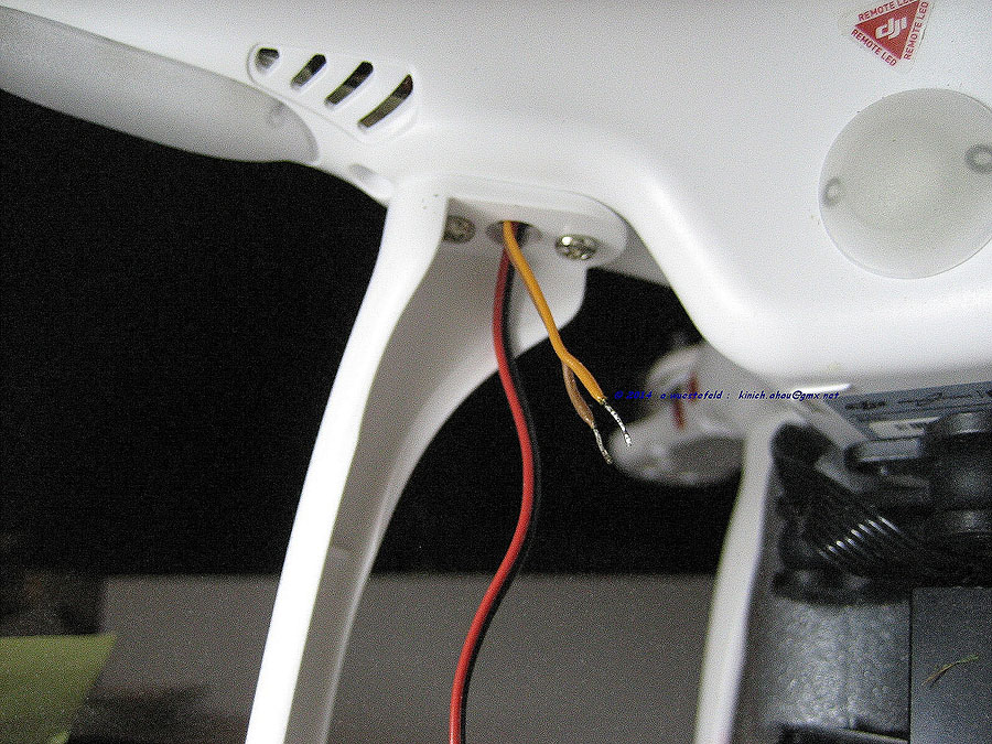
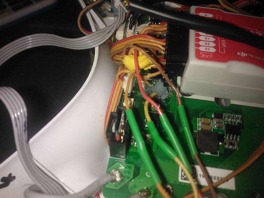
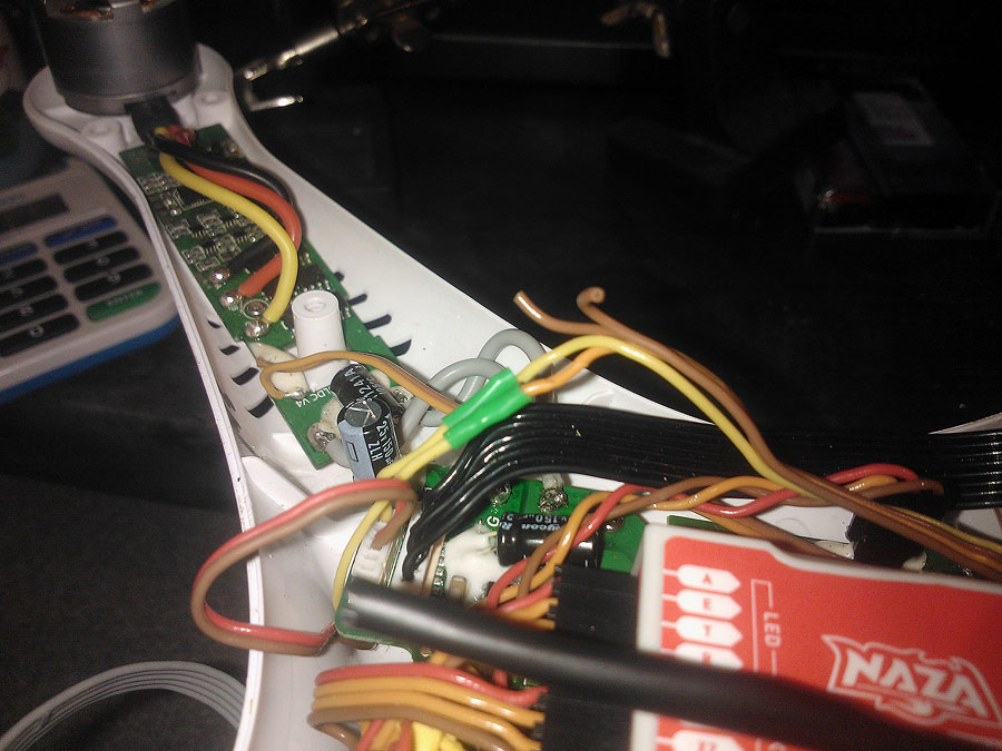
This is image came from Marcus Dawson, he modified his Phantom 1 to put iOSD mini inside. He cut a cable and direct solder into main board. Please see below image and description from him :-)
“Shows the joined cables with orange on the left and yellow on the canbus ports (and my huge blob of silicone covering the points.)”
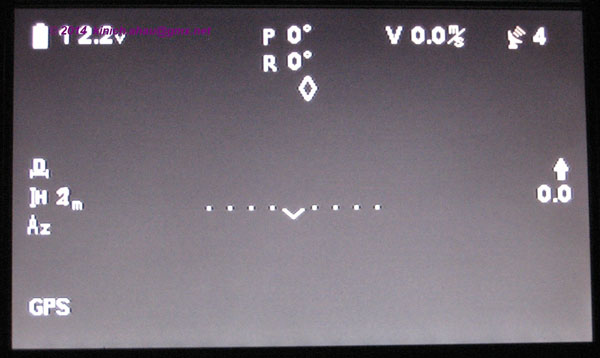
“shows the iOSD connected up via my canbus cable. You can see where I’ve lopped the original connector off the end. Again, in hindsight I could have left it on.”
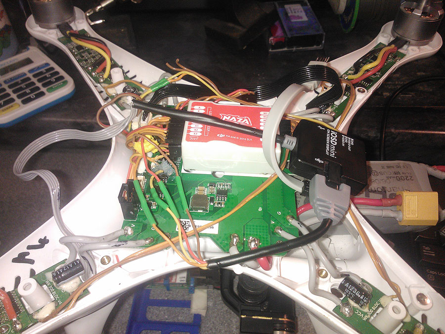
“Shows the video connection. I’ve pulled the yellow wire ‘off’ the zenmuse ribbon. Cut it and inserted the iOSD cables in here. It’s yellow off the board to iOSD yellow and then iOSD orange to yellow going to FPV TX.”


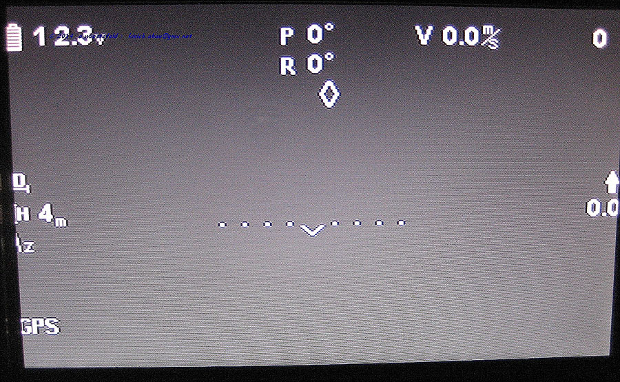
Will all the GPS info show on iosd mini display on fpv ex speed, satellites, distance
In doing this upgrade does the GPS, Speed, Satillite info all come up.
You will get all feature that iOSD mini provided. (You must have iOSD)
Nice job I just picked up a iosd mini will try tommorrow
Well I installed everything with one issue I go to power up and readings show up and gimbal goes to power up then goes limp.
When I unplug the battery and replug it in with the RV wire disconnected the gimbal works again and no FPV
Any one encounter this.
Hi Sarawuth,
I think I have also toasted my upgrade board, CL gold contact has detach from the board, before purchasing another board is there any other contact points I could try and solder to, I noticed in a previous post the same thing happened to Serge and you mentioned it may be possible to solder to the IC Pin, is it possible you can point me in the right direction of this IC Pin please.
Kind regards
Sparko
England
EricPeniata – I am experiencing something similar. I have IOSD, Zenmuse, AVL58. When everything is hooked up and I plug in my 3S lipo, the GoPro will power on, but the H32D is limp. I power off, I disconnect the IOSD, power on, wait for H32D to initialize, plug in IOSD and then everything works. Sometimes everything will work right from power up. I have mine setup where the IOSD is on the exterior and I have a mini harness so I can quick detach the IOSD. I haven’t been flying much so I haven’t tested much but those were my findings from 4 flights.
Also can anyone comment on using 4s batteries? My Phantom can fly with 4S on the upgrade board but the Zenmuse won’t initiate.
Found the fix I adjust my tilt perimeters prior to this hack. Found if the camera is pointed at 90 degrees to facing down I have no gimbal power issues. If camera is above 90 or facing up towards aircraft it doesn’t not power. I just power up with camera at 45 works every time…….. weird
David,
From this picture. http://www.sarawuth.com/2014/01/dji-phantom-1-modify-to-have-can-bus-port/phantom1_hack/#main
you’ll see a chip below CL, CH point. It’ve 4 pin on each side. The pin 2,3 on chip is CH, CL point. But it’s really hard to solder.
Sarawuth,
Thanks your for your help I’m extremely grateful, hopefully I have managed to save the board and after about 3 or 4 attempts I have successfully managed to form a small bridge of solder onto pin 2,3 on the chip and attach the leads as shown in your pictures submitted by Andreas,hopefully the rest of the soldering will now go without a hitch, big thank you for sharing your ideas.
Tip for anyone that has done the same to their board I used X8 magnification headset along with a very bright led light and a Hakko FX-888D solder station with a fine tip set to 200 centigrade for CH,CL point, but GRD, and RV point required 250 centigrade to melt existing solder.
Hello Sarawuth,
First of all i want to thank you very much for your help. My phantom 1 become like phantom 2. I have one issue that i couldn’t sort out. How can i get power from phantom battery for video transmitter when using iosd mini ? (FPV port from the upgrade board has 1 gnd,1 video signal, 1 vcc pin. Gnd and video signal goes to iosd mini. Vcc goes to video transmitter but there is no gnd left to bind it to video transmitter).
Kind regards
Cenk
Cenk,
My VTx can work with 12V so I have soldered an extra cable (black and red) to the Board where the Main Power cable from Lipo-cable is soldered, on the picture (you can see if you know where to look) it is around below the Futaba receiver, but then you can see the red / black cable leading to left side upwards to the upper left leg outside to power the VTx. I am NOT using the Vcc from the FPV Port of the upgrade board. As you see on the pics I use only the yellow and brown cable, the red one is dead. So you probably simply need one extra GND from the Lipo-GND to your VTx. Take your choice.
Hope this helps.
Andreas
Hi sarawuth, your tutorial has really helped me ! Thank you very much. My phantom 1 is now perfect! My iosd mini is working well and I have also connected the 2.4GHz datalink. All is working well. However my iPad mini retina will not connect to the ground end btu. I have done some research and according to forums that I must wait for the latest firmware from dji to enable the connection of my iPad mini retina to the btu ground end. Is there any other way to go about this? Would really appreciate your help on this if you know any. Thanking you in advance for your cooperation. Regards Rizal from Kuala Lumpur.
Thank you :-) For iPad connection. Please make sure you upgrade all firmware to latest version. iBTU, Datalink (Both Ground/Air unit). And please try again.
Hi sarawuth, thank you for your reply, i have upgraded to the latest firmware on ibtu, data link etc but still cant connect. Apparently infos i gather from forums suggests that i must wait for the latest firmware that is yet to be available. Thank you anyways.
incroyable, vous êtes un véritable artiste. Superbe travail
Hi Sarawuth, I am almost finished with a complete rework of the phantom 2 vision. I have switched the stock camera for a H3 2D zenmuse gimbal and go pro. Tonight I added the AVL58 transmitter connecting through the DJI FPV hub. Everything is working great. Next I want to add in the mini iosd.
I can plug the video into the FPV hub, but the PV2 does not have a CanBus port to plug into.
I traced the CanBus connector on a non -vision Phanton 2, and see the 4pin port on the board where the canbus connects to. That port is exactly the same on the p2v but currently empty. I have the exact 4pin connector on a four wire ribbon. Now I need to connect the four wires to a CanBus connector. Do you have any clues on the wire layout or any other thoughts on connecting it?
Thanks,
Craig Thompson
Any reason why one shouldn’t just chop off the canbus plug on an iosd mini and solder them directly to the board? Would save a (tiny) bit of weight and probably a little bit of space. Would mean the unit is fixed and cannot be unplugged but I can’t see what problem that would cause.
Thanks,
Marcus
Marcus, no reason. You can do that :-) But for me. I’m planned for using it with other quad, so I try to keep it as original.
Instead of removing epoxy and soldering on the board, would be same connecting on “to X3 port” cables? I mean your white to X3 red and your grey to X3brown?
A **note** To anyone doing this mod. When soldering CH and CL, try not to tug vertically as the trace point is quite delicate and easy to lift off the board. I notice at least two other people commented on “burnt or damaged” CH and CL points. I have damaged mine while “tugging” on the wires. I now soldered to the IC pins 2 and 3. Its a poo poo to solder and secure, but seems to work ok.
So I followed the excellent instruction set… Those ch/cl solder points are tiny, slightly smaller than un boiled spaghetti!
I deviated slightly from the plan above in that I chopped off the can bus port and, using the plug to connection diagram, connected the wires that way.
That is my first bit of experimental hindsight… When I got the zenmuse/board upgrade I got a female to female CABBUS cable in with one of these parts. *SHOULD* have chopped that in half and wired the CANBUS ‘curcuit’ backwards. Then I could have removed the iosd, if required, quickly and easily.
Managed to get everything soldered up and suitably insulated.
Another note that may have been useful would be continuity test points, as mentioned above a couple of the IC pins are also cl/ch points. I could then have checked connections before applying power.
So… After a visual double check I plugged up the battery, got the beep tune and a few moments later the fpv came alive and there was the the iosd display over the go pro data… Success!
It was a few moments later that I noticed I only had the isod display but no actual data. When I lifted the phantom the attitude/horizon bar did not move, but the gimbal pitched correctly.
I am doing all of this indoors so I wasn’t expecting any gps data, also the lid was off the quad, so the gps and compass were at 90deg to the quad.
What I also subsequently noticed was the LED switching between green and half brightness green and eventually switching to solid green.
I did wonder if any of this was down to my indoors location so I popped the lid back on and went outside.
Sadly the same again, flashing green (solid/half brightness never going out) and no ‘data’ on the iosd display. Motors still.power up and obey remote commands, tested without props.
Now guessing something was wrong, even though the iosd led was flashing green and, I think, sometimes solid green, I disconnected the iosd.
But still the same green light combination… And now no communication with the Naza and PC via USB
I am guessing that somewhere along the line I fried the CANBUS lines and that has done something ‘bad’ to the main board.
But does anyone else have any comments or suggestions please?
I am guessing I will need to get a new main board (please let it not be the Naza :( )
Things I will probably look into:
* Are the cl/ch points available on the underside of the board?
* Connecting the female/female CANBUS cable instead of direct soldering.
* Continuity testing the install before power.
Live and learn, hopefully my failure and (when I’ve redone things next week) sucessful install will aid everyone else doing this fantastic update.
Cheers,
Marcus
Update on my situation… It looks like I’ve been a muppet..
The LED and EXP leads were plugged into the wrong sockets on the Naza (bangs my head on wall)
Have to go out but will experiment later and report back.
Hi Marcus & Kevin, could you both post-link pictures of yr soldering?
Thanks
great job!!!
I have a phantom FC40 (meaning 5.4GHz tx and 2.4WiFi VC40 camera)and would like to add 2.4G BTU Ground Station, can I use yourinstrctuions to to that? Do I have to buy the P330-H3-2D board… or better is the P330-H3-2D board compatible with my phantom FC40?
thanks,
Antonio (from Italy)
Hi Antonio, can you check the board inside your phantom. Maybe you already have P330-H3 board.
Can you tell me where you purchased the green plug you used to connect the iosd mini to the main board. I’m having difficulty finding anything that will connect. I’d rather not cut or destroy the unit. Thanks much for this post.
Sarawuth, Thanks for your post it has helped me alot, I wish I would have found it days ago,,, I have the same question as before,,, IF I just cut the end of the ISOD mini, and soldering the wire straight to the P330 board, How do I know what color of wire goes to the spots you show?? Or how do I know which wire does what inside the IOSD mini,, are they all the same and in the same order?? Again,, Thanks for all your help.. John
I might be able to help with that one.. I did try and do the end chop, but it didn’t work straight off.. See my earlier ‘I’m a muppet’ post.
The pinouts for the Canbus plug are on an image at the top of the page. Once I had a can bus lead with bare ends it was a simple case of using a multimeter to buzz out the pins to the cables.
rv – red
gnd – brown
ch – orange
cl- yellow
You can ASSUME the cables are the same colour in your cables.. But you might make an ASS out of U and ME :-) always worth checking if you can.
So I thought about expandability and removability. I had a spare female to female canbus cable from either the P1 upgrade kit or the Zenmuse install kit. I chopped this in half and now I have a canbus plug on my mother board. This then plugs into the iOSD and it all works :-)
For the power (rv/red / gnd/brown) I didn’t de solder the cables but instead stripped back the plastic sheath and soldered wire to wire. Then I covered it all up with Sugru (search for it.. Fab stuff).
The ch and cl cables I did have to solder to the board. I can not stress enough how small these points are.. Think uncooked spaghetti end. For ease I soldered on bare wires to this. Made holding things easier. I just used a short length of the canbus cables for the right colour. Once the two wires were attached to the board I siliconed them on to add extra grip/insulation/faith. Easy then to solder the Canbus plug to the wires.
If I had NOT chopped the iOSD canbus plug off then I would have had an expandable system (BTU?) but then I suspect the next unit will come with a plug and the iOSD can remain at the end of the chain.
As for the video side of things I just pulled apart the Zenmuse video ribbon cable, chopped the yellow wire (wow that sounds like bomb disposal!) and wired in the video in and out accordingly. Didn’t bother with the gnd as after all 0v is 0v and we’ve already got that on the Canbus connecting the iOSD.
If Sarawuth wants to drop me a mail I can forward images for this page. :-)
As a visual person I’d like to see pictures in order to understand clearly. I’m about to embark on this journey this evening. Like to do it right. Thanks for help.
Marcus, feel free to send it to sarawuth@gmail.com ;-)
you got mail :-)
Thanks Marcus, That would be great, after I thought about it for a minute, I could just test each wire at the ends to see which wire is where in the pin,, Hopefully they used the same color code thru out there cables, that would help alot,, I like the idea of useing a female end to solder to the board, that way the IOSD mini stays intact.. Again thanks for all your help.. John
I have a question.
Tr Immersion 600mw supply output 5v ~ 300mAh.
Could this power DJI MiniIOSD?
@Marcus
“that sounds like bomb disposal!) and wired in the video in and out accordingly. Didn’t bother with the gnd as after all 0v is 0v and we’ve already got that on the Canbus connecting the iOSD.”
Planning to use ESC GND soldering point, have to desolder-resolder anyway replacing the motherboard.
@matt_v939 If you see me running try and keep up [ Bomb disposal motto :-) ]
When I did all this I’d already changed main boards. If I was doing all this at the same time I would probably have looked to connect the can bus cable before I even put the board in the case. Less fiddly and better places to hold the board when soldering I’d imagine.
Thank you very much. I’ve also encouraged to do so.
http://intrepi2puntocero.wordpress.com/2014/04/15/modificando-placa-de-control-phantom-canbus/
PeRRo__RoJo is there any way to translate your post to English?? I would love to read what and how you did this,, Thanks,, John
John, you can use google translate:
http://translate.google.com/translate?sl=auto&tl=en&js=y&prev=_t&hl=en&ie=UTF-8&u=http%3A%2F%2Fintrepi2puntocero.wordpress.com%2F2014%2F04%2F15%2Fmodificando-placa-de-control-phantom-canbus%2F&edit-text=
Sorry,
I was planning to do the mod but I’m a little bit concerned about the problems evidenced here in case of using zenmuse in combination with avl58. Is there any confirm ?is about eventually questions of firmware? Or maybe not good isolation in the new contacts? I bought iosd mini and now I’m a bit worried cause everything before make the mod is working perfectly.
if i do this on my FC-40 and connect a mini iosd, do i have to add fpv system to see the telemetry or is there a way to get it without fpv?
Sarawuth,
Does the NAZA Lite therefore have the capability to accept waypoints? I thought this is only possible with the NAZA V2.
Regards
Pierre
Hi Sarawuth and guys,
first time i am ever doing anything in electronics
i am not sure if i have done any harm to my board,
some people like David Smith and serge here told that the “CL gold contact has detach from the board”
I was using a very bad solder ( very low temp ) and it has start to be messy.
after some tries the gold contacts weren’t gold any more they have turn silverish.
is that mean that they are gone ??
from that point i had very tough time trying to solder it (2 hours ).
then a friend comes by and brought me his solder,
i have then manged to solder or attaching the wires to there place. (cl ch)
is there a way i can check to see if the connection is working ?
Sarawuth suggest to to solder the cl ch to the chip in the picture ,
is that means i should see a connection on a current meter between the chip 2,3 leg to the wires i had solder?
if i did burn it
what is leg 2,3
do i count the legs from the left (in the picture ) wich means 2 middel legs are cl , ch ?
what is so hard to solder there (chip work around) ??
in case its working either way can i place hot glue on the cl , ch points in the end ??
thanks
Gilad
Hello guys,
Thank you all for your participation, it is so interesting. I have also did the modification on my Phantom 1 with the upgrade motherboard.
Unfortunately, with my hero 3+ on my h3d2, when i plug the ch and cl (iosd mini) my ginball doesn t initialized…. I have the image from my camera on my screen, but can not get my camera align on the horison. I use the original cable of the motherboard, the grey one, and i get the video signal from the motherboard. Any chance to fix that problem?
Thanks to all!
Cedric
I dont know the answer and didnt get answer to my quistion for 3 weeks ,
Its look like this forum is a sleep,
But i did read something about what u r expirencing .
Look for it in the comments …
Something about disconnecting some of the components and then reconnect them .
Please let know what did you came up with
I am on my way making this mod and its nice to have someone to talk to about it :-)
I did modifued my board , after i had some problems welding cl i had to weld it to the chip .
Now its done but i stalling with the rest untill my p2 shell will arrive next week …
Gents, relax !
at least I still follow the comments, but if the questions are from that nature that I have no answer, why should I write “I have no answer ” ? e.g. for measuring in case of Gilad: my copter is closed after I had installed additional LEDs and I am happy that he is closed and I don’t want to open him as long as it is not needed due to technical problems. Similar in case Cedric: I simply have no idea, in my case there is not such effect. There might be different reasons possible, just check one by one.
If somebody get no answer, then the it seems there is actually nobody available who can help. It was very clear, that for such soldering mod good knowledge is needed – it might be risky for those colleagues not firm with soldering, but its worth to do because it works !
Can just recommend again to be VERY carefully with soldering on the board. It is very sensible.
Good luck,
Andreas
I am not sure why you are being so protective ,
I have say nothing against nothing , only say forum is sleep
And thats cool for no answer.n
I solved my problem so far, it is hard but doable .
I wel it to the chip
I am still not sure if i kiled the board or not.
I have tested all weirs , nothing is more then 5.5v
So it looks fine , i am wating for my phantom 2 shell to test ut real .
Any way no need to open you rig
The guy just ask about a problem
I think i sew some one mention the same problem , actually 2 of them ,
I am with my phone so its hard to look it up.
But the had a sulotion.
Lets keep it frendly huh :-)
Oww yea if any body intersted after getting a good support from rc group , i can tell that all wires coming out of thus board shuld be no more then 5.5 v
Allso wire coming in to naza could be between 0 to 5.5 , my is 0.7 and thats fine ,
Its actually disabled and naza dont use it . i will post here exact detail of what i am talking about sens i am a noob and trying to repeat what i have been told :-)
Lol so tomorow i will post data of the board incase some one wants to know if board will risk his component
After moding
@Gilad: everything in good order: maybe my wordings left a wrong impression.
Happy flights !
I am going to do the sarawuth mod,the thing that got me thinking is this quote from the sarawuth blog, made by Marcus Dawson ¨ When I got the zenmuse/board upgrade I got a female to female CABBUS cable in with one of these parts. SHOULD have chopped that in half and wired the CANBUS ‘curcuit’ backwards. Then I could have removed the iosd, if required, quickly and easily¨ How exactly would this work?
For that im going to use a female can bus cable conected to the mini iosd thru the empty can bus in of the mini iosd, cut and solder in the board the Ch and Cl cables, but im in doubt how to manage the other two, can i splice the cable with the GND and RV and conect it directly to the x3 without soldering them directly to the board? What happends to the can bus cable the comes attached to the mini iosd with this method?
Has anyone try this, any pictures or video?
Thanks
What is your opinion about it? Thanks again