DJI just release Phantom 2 with extra feature to have CAN Port expansion on their leg. Also the physical of Phantom 2 is far different than Phantom 1. Bigger battery, 9″ propeller, CAN bus port expansion.
But for me. I still don’t want to upgrade. I have Zenmuse H3-2D and not able to use with Phantom 2 because mount is not compatible and DJI don’t sell mount separately. And I have many battery for old Phantom.
Then my target is modify current P330-H3-2D main board to have CAN Bus. I think DJI still use CAN protocol between equipment. So, It should possible to hack their main board.
– I tear apart my DJI PMU-V2 and check it’s schematic on CAN port. I found it have 4 pin (Regulated Voltage, GND, CH, CL). The CH (CAN High) and CL (CAN Low) pin attach to one IC on PIN 2, 3.
– Back to P330-H3-2D board. Please focus on the my pink circle mark. This is the place for do modification.

– Use cutter or any tool to remove epoxy on GND, Regulate Volt PIN as I show.
– Use a small screw driver scratch and remove protection film on CH, CL circle mark.
– Please use small tip soldering iron if possible. You may damage your board if your soldering iron is too hot! (Thanks Roderick on Facebook for this concern).
– Solder four wires to GND, RV, CH, CL mark as I show on below picture. I’m using White as Regulated voltage, Gray as GND, Blue as CL and last wire as CH.
– Please keep in mind RV is not battery voltage! it’s REGULATED voltage!
– Please apply some epoxy to fix the cable and prevent short circuit :-)

– I put other side of cable outside Phantom 1. I don’t have their CAN Bus port and don’t know where to find it in Bangkok. :-(
– (Update) I knew how to get port. It’s a workaround solution but good for anyone who plan to use FPV. You can take a part iOSD mini and solder four wires direct to iOSD mini. And you will have DJI official CAN Port as below picture :-D
– Please be careful on plug it into DJI cable. Cable must be in Reg-Volt, GND, CH, CL order.


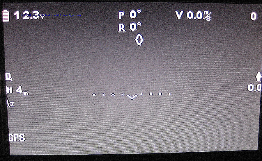
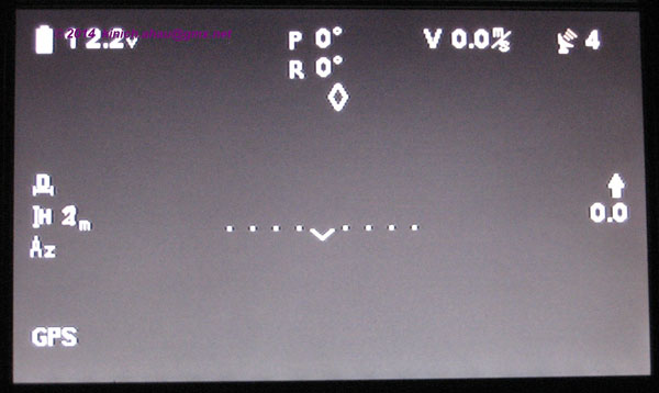
– Done! now your Phantom 1 with P330-H3-2D board will able to plug *ANY* DJI equipment. iOSD Mark 2, iOSD Mini, iBTU, 2.4GHz module, etc. I’m using it with 2.4GHz with iBTU and iPad on below picture.


I hope you will able to follow my instruction and have fun with flying the old Phantom.
มีความสุขในการบินกันทุกคนนะครับ :-)
Modification picture from our friend Andreas. He have a great idea for put his iOSD inside phantom but instead of direct solder four cables into board. He use JST male/female to hook it.
He cut JST cable into two as below picture.
Solder the female cable on P330 main board.
And solder mail cable on iOSD board. (Please do *DOUBLE CHECK* on RV and GND point)


And this is inside his phantom.
Four wire for plug to Video link. Red = Volt, Black = GND.
And he also adjust the OSD icon location on assistant software then ready to fly !! Thank you very much Andreas.


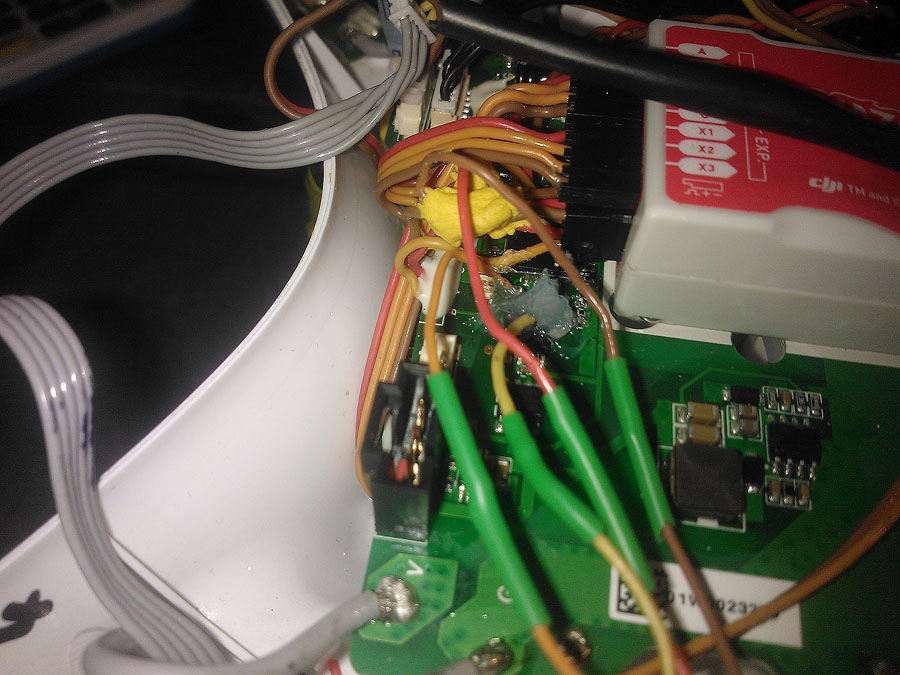
This is image came from Marcus Dawson, he modified his Phantom 1 to put iOSD mini inside. He cut a cable and direct solder into main board. Please see below image and description from him :-)
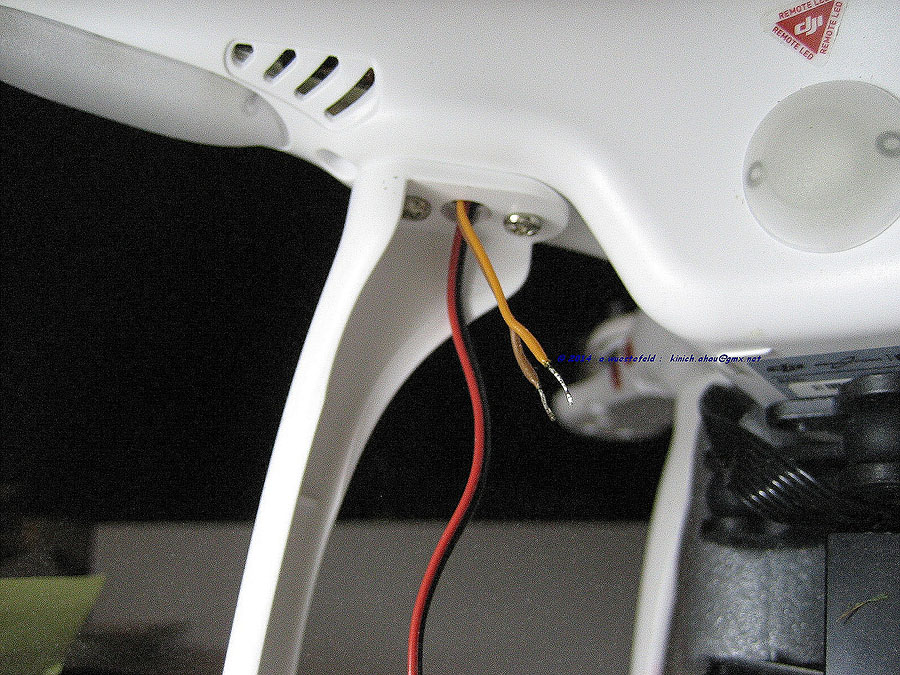
“Shows the joined cables with orange on the left and yellow on the canbus ports (and my huge blob of silicone covering the points.)”
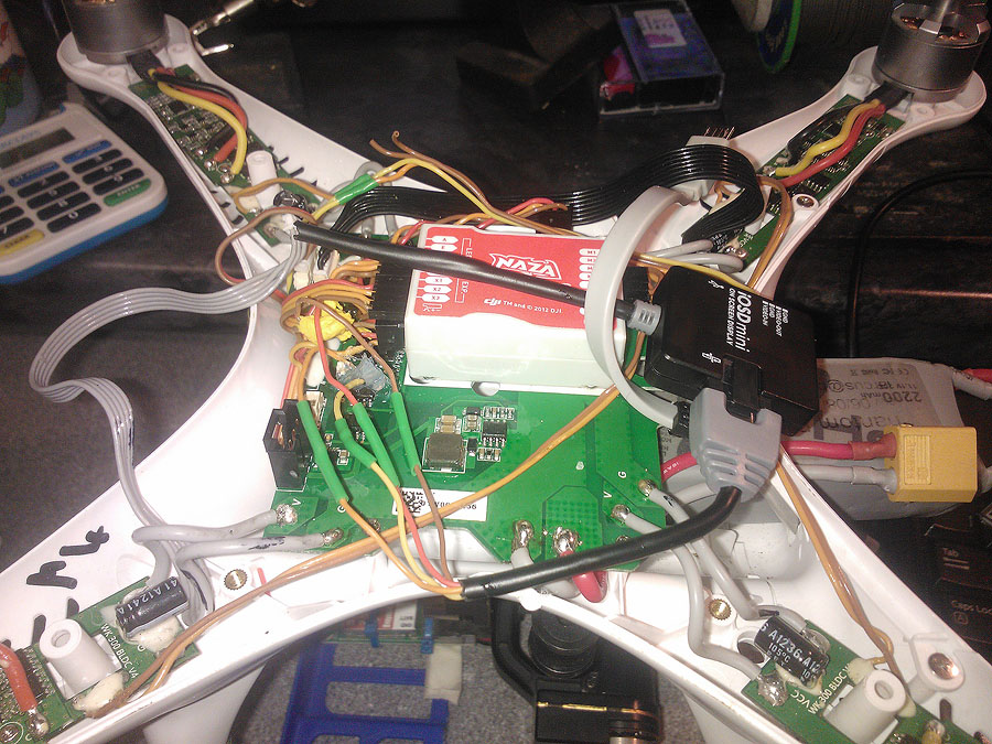
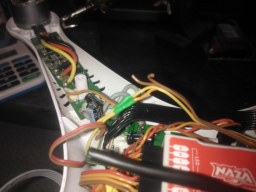
“shows the iOSD connected up via my canbus cable. You can see where I’ve lopped the original connector off the end. Again, in hindsight I could have left it on.”
“Shows the video connection. I’ve pulled the yellow wire ‘off’ the zenmuse ribbon. Cut it and inserted the iOSD cables in here. It’s yellow off the board to iOSD yellow and then iOSD orange to yellow going to FPV TX.”


I am sorry i am really trying to understand but i dont
@David. I’m a bit lost as to what the “x3” is?
The only difference between what I ACTUALLY did and what I SHOULD have done is that I cut the iOSD cable. My first ‘go’ was soldering the iOSD directly to the board, I then soldered the cut half of the iOSD cable (with the proper plug) to the board.
If I had thought it through, and what I would do next time, is leave the iOSD intact, cut the female to female cable in half and use that to make the circuit board connection. You would end up with a ‘backwards’ CANBUS system, but since it’s just a daisy chain loop that wouldn’t matter.
Hope this helps,
Marcus
Pingback: Phantom 1 upgrade to support H3-2D gimbal, iOSD mini and Wireless video transmitter
¿Is it possible to do this mod for a phantom fc40?
Hello to all,
Modification done…. Perfect for the informations from the iosd and the gainball…. so thanks to all…!!!! . BUT, my Phantom make me sick when i watch at him flying, as it is very bumpy in its yaw axe…did you change your gain on the software after that modification?
Thanks to all!!!!
Cedric
Hi there,
Do you have the protocol to control the gimbal by can bus? I have some id values to control the gimbal.
Like
0x200
0x201
0x205
0x206
0x207
0x208
0x209
0x20A
0x20B
Do you have some this results when analyse the gimbal?
I just did it thanks alot works perfect on a my dji phantom 1.1.1 with naza v2 and h3 2d zenmuse board beautiful !!!!!
Another thing i used the same jst cable above and i slighty forced in the can bus plug on the iosd in the female jst plug it works !!! So i left the iosd intact no need to cut the wires only the jst male !!! I don t know how to upload the pictures so i can show you all
Maurizio, Please may you tell me what main board do you have? I have the original main board 1.1.1, the NAZA v2 and it looks different from the one in the picture. Saluti
Thanks so much!! I now have 2.4g data link and ground station working on my old phantom, fantastic!!
I’m happy too :)
Sarawuth
sarawuth, could be great if you can add some extra switch or exstra function to the drone, i mean, in fly, if you press some extra buttom, then the drone open/close some analog/digital I/O… for what? think, it could be a drone fighter. if you put sime fireworks like this rocket/missiles http://www.pyrouniverse.com/consumer/types.htm then with some 3v incinerator we can start the ignition and shoot in air-to-air drone firework !!
the incinetator can be easy made with the old lights of the xmas pines lights, take some bulb and put in the fire then put in warer to broken only the glass, then the filament is intact and it will burn for ignitiate the firework!
If I connect my iosd that way, my zenmuse gymbal doesnt work.
Whats the problem?
Since the weather is nice, I just wanted to say Hello again and hope everyone’s Winter drone projects are wrapping up and ready for the Spring/Summer =P I have sold my Phantom, but kept the upgrade board as It continues to be a wonderful interface into DJI enthusiast drone products.
I’ve been reading through forums for days and couldn’t find a solution yet. I have a Phantom 1 v1.1.1, on which I installed the upgrade board for h3-2d gimbal and then I mounted a H3-3D gimbal. The gimbal works but the gimbal lever that controls the pitch of the camera, works in incremental mode: When i put the lever in 0 Position (middle), the gimbal remains in fixed position. When I move the lever up, it goes up till the end. When I move the lever down, it goes down till the end. I want the camera to follow the lever position. When the lever is in the middle, the camera should be also in the middle. When the lever is UP, I want the position of the camera to be horizontal. When the lever is DOWN, I want the positition of the camera to be film the ground (all way down). Do you think I have any chance of doing this on the Phantom 1? It is very difficult to control the gimbal now, because if the lever is not on the 0 position (even +3 or -3 shown on the respective channel in the assistant, makes the gimbal to slowly move UP or DOWn until it reaches the end. I have the latest NAZA-M V2 firmware (4.04)
Hello all,
How do you control the gimbal tilt from the remote lever? I have phantom 1 v1.1.1 and upgrade board for h3-2d with h3-3d gimbal. The lever works only in incremental mode and not in follow position mode. Any ideas what to modify? Thanks!
Thanks for the mod instructions.
One thing I did differently was soldering a servo plug to the Gnd & regulated voltage of the OSD and plugged that into a spare channel on the Naza rather than scraping off the silicone & soldering to the board. The CAN bus wires I did exactly as you described.